Table of Contents
Nftables - Netfilter and VPN/IPsec packet flow
In this article I like to explain how the packet flow through Netfilter hooks looks like on a host which works as an IPsec-based VPN gateway in tunnel-mode. Obviously network packets which are to be sent through a VPN tunnel are encrypted+encapsulated on a VPN gateway and packets received through the tunnel are decapsulated and decrypted… but in which sequence does this exactly happen and which packet traverses which Netfilter hook in which sequence and in which form (encrypted/not yet encrypted/already decrypted)? I'll do a short recap of IPsec in general, explain the IPsec implementation on Linux as it is commonly used today (Strongswan + Xfrm framework) and explain packet traversal through the VPN gateways in an example site-to-site VPN setup (IPsec in tunnel-mode, IKEv2, ESP, IPv4). I'll focus on Nftables in favor of the older Iptables and I'll setup the VPN via the modern Vici/swanctl configuration interface of Strongswan instead of the older Stroke interface.
IPsec short recap
A comprehensive recap on the topic IPsec would require an entire book. I'll merely provide a very short recap here focused on protocols and ports to put my actual topic into context.
IKE protocol
An IPsec based VPN possesses a “management channel” between both VPN endpoint hosts1), which is the IKE protocol2). It is responsible for bringing up, managing, and tearing down the VPN tunnel connection between both VPN endpoints. This gives both endpoints the opportunity to authenticate to each other and negotiate encryption-, authentication- and data-integrity-algorithms and the keys those algorithms require (usually session-based keys). IKE is encapsulated in UDP and uses UDP port 500. In case of NAT-traversal (= if a NAT router is detected between both endpoints during IKE handshake) it dynamically switches to UDP port 4500 during IKE handshake. Thus, IKE encapsulation on an Ethernet-based network looks like this:
|eth|ip|udp|ikev2| | IKEv2 packet on UDP/500, Nat-traversal: UDP/500 → UDP/4500 |
SAs and SPs
The mentioned algorithms and keys which are negotiated during IKE handshake are being organized in so-called Security Associations (SAs). Usually there are (at least) three SAs negotiated for each VPN tunnel connection: The IKE_SA which, once established, represents the secured communication channel for IKE itself and (at least) two more CHILD_SAs, one for each data flow direction, which represent the secured communication channels for packets which shall flow through the VPN tunnel.
In addition to the SAs, IPsec also introduces the concept of the so-called Security Policies (SPs), which are also created during IKE handshake. Those are either defined by the IPsec tunnel configuration provided by the admin/user and/or (depending on case) can also at least partly result from dynamic IKE negotiation. The purpose of the SPs is to act as “traffic selectors” on each VPN endpoint to decide which network packet shall travel through the VPN tunnel and which not. Usually the SPs make those distinction based on source and destination IP addresses (/subnets) of the packets, but additional parameters (e.g. protocols, port numbers, …) can also be considered. If a packet shall travel through the VPN tunnel, the SP further specifies, which SA is to be applied.
Be aware that both SAs and SPs merely are volatile and not persistent data. Their lifetime is defined by the lifetime of the VPN tunnel connection. It might even be shorter because of key re-negotiations / “rekeying”.
ESP protocol, tunnel-mode
After the initial IKE handshake has been successfully finished, the VPN tunnel between both endpoints thereby is “up” and packets can travel through it. In case of tunnel-mode the IP packets which shall travel through the VPN tunnel are being encrypted and then encapsulated in packets of the so-called ESP protocol3). The whole thing is then further encapsulated into another (an “outer”) IP packet. The reason is that the VPN tunnel itself is merely a point-to-point connection between two VPN endpoints (one source and one destination IP address), but those endpoints are in that case VPN gateways which are used to connect entire subnets on both ends of the tunnel. Thus, the source and destination IP addresses of the “payload” packets which travel through the VPN gateway need to be kept independent from the source and destination IP addresses of the “outer” IP packets. Encapsulation then looks like this (example for a TCP connection):
|eth| |ip|tcp|payload|4) | A “normal” packet which shall travel through the VPN tunnel, is encrypted and encapsulated like this while traversing the VPN gateway. |
|eth|ip|esp|ip|tcp|payload|5)6) |
If Nat-traversal is active, then ESP is additionally encapsulated in UDP:
|eth| |ip|tcp|payload| | In case of Nat-traversal additional encapsulation in UDP (same port 4500 as for IKE is then used here). |
|eth|ip|udp|esp|ip|tcp|payload| |
IPsec Linux implementation
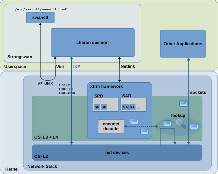
IPsec implementation in Linux consists of a userspace part and a kernel part. Several implementations have been created over the years. Nowadays the most commonly used implementation of the userspace part seems to be StrongSwan (There were/are other implementations like Openswan and FreeS/WAN. I'll focus on Strongswan here.) The IPsec implementation in modern Linux kernels is the so-called Xfrm framework, which is sometimes also called the Netkey stack. It is present in the Linux kernel since v2.6. There have been predecessors, like the KLIPS IPsec stack which was used in kernel v2.4 and earlier. With Figure 1 I like to show the responsibilities of Strongswan and the Xfrm framework and how both interact with each other in a simple block diagram style.
Stongswan
The essential part of Strongswan is the userspace daemon charon which implements IKEv1/IKEv2 and acts as the central “orchestrator” of IPsec-based VPN tunnels/connections on each VPN endpoint host.
It provides an interface to the user/admin for configuration of IPsec on the system.
Actually, more precisely, it provides two different interfaces to do that:
One is the so-called Stroke interface. It provides means to configure IPsec
via two main config files /etc/ipsec.conf and /etc/ipsec.secrets.
This is the older of the two interfaces and it can be considered deprecated
by now (however it is still supported).
The other and newer one is the so-called Vici interface. This is an IPC mechanism,
which means the charon daemon is listening on a Unix domain socket and client tools
like Strongswans own cmdline tool swanctl7)
can connect to it to configure IPsec.
This way of configuration is more powerful than the Stroke interface , because it
makes it easier for other tools to provide and adjust configuration dynamically
and event driven at any time.
However in many common IPsec setups the configuration is still simply being
supplied via config files. When using Vici, the difference merely is that
the config file(s) (mainly the file /etc/swanctl/swanctl.conf) are not interpreted
by the charon daemon directly, but instead are interpreted by the cmdline tool swanctl
which then feeds this config into the charon daemon via the Vici IPC interface.
Further, the syntax of swanctl.conf looks slightly different than the syntax
of ipsec.conf from the Stroke interface, but the semantic is nearly the same.
An additional config file /etc/strongswan.conf8) exists, which contains general/global strongswan settings, which are not directly related to individual VPN connections.
So let's say you created a swanctl.conf config file on both of your VPN endpoint hosts with the intended configuration of your VPN tunnel and you used the swanctl tool to load this configuration into the charon daemon and to initiate the IKE handshake with the peer endpoint9). The charon daemon, when executing the IKE handshake, negotiates all the details of the VPN tunnel with the peer as explained above and thereby creates the SA and SP instances which define the VPN connection. It keeps the IKE_SA for itself in userspace, because this is its own “secure channel” for IKE communication with the peer endpoint. It feeds the other SA and SP instances into the kernel via a Netlink socket. The VPN connection/tunnel is now “up”. If you later decide to terminate the VPN connection again, charon removes the SA and SP instances from the kernel.
The Xfrm framework
The so-called Xfrm framework is a component within the Linux kernel. As one of the iproute2 man pages10) states, it is an “IP framework for transforming packets (such as encrypting their payloads)”. Thus, “Xfrm” stands for “transform”. While the userspace part (Strongswan) handles the overall IPsec orchestration and runs the IKEv1/IKEv2 protocol to buildup/teardown VPN tunnels/connections, the kernel part is responsible for encrypting+encapsulating and decrypting+decapsulating network packets which travel through the VPN tunnel and to select/decide which packets go through the VPN tunnel at all. To do that, it requires all SA and SP instances which define the VPN tunnel/connection to be present within the kernel. Only then it can make decisions on which packet shall be encrypted/decrypted and which not and which encryption algorithms and keys to use.
The Xfrm framework implements the so-called Security Association Database (SAD)
and the Security Policy Database (SPD) for holding SA and SP instances.
An SA is represented by struct xfrm_state and an SP by struct xfrm_policy in the kernel.
Userspace components (like Strongswan, the iproute2 tool collection and others) use a Netlink socket to communicate with the kernel to show/create/modify/delete SA and SP instances in the SAD and SPD. You can e.g. use the iproute2 tool ip to show the SA and SP instances which currently exist in those databases:
- command
ip xfrm stateshows SA instances - command
ip xfrm policyshows SP instances
You can further use ip as a low-level config tool to create/delete SA and SP instances. There is a very good article which explains how to do that. However in practice you leave the duty of creating/deleting SA and SP instances to Strongswan.
SP instances can be created for three different “data directions”:
| security policy | syntax11) | meaning |
|---|---|---|
| “output policy” | dir out | SP works as a selector on outgoing packets to select which are to be encrypted+encapsulated and which not |
| “input policy” | dir in | SP works as a selector on incoming packets which already have been decrypted+decapsulated and have a destination IP local on the system |
| “forward policy” | dir fwd | SP works as a selector on incoming packets which already have been decrypted+decapsulated and have a destination IP which is not local, thereby packets which are to be forwarded |
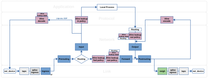
If you are working with Nftables or Iptables, then you probably are familiar with the widely used Netfilter packet flow image, which illustrates the packet flow through the Netfilter hooks and Iptables chains. One great thing about this image is, that it also covers the Xfrm framework. It illustrates four distinct “Xfrm actions” in the network packet flow path, named xfrm/socket lookup, xfrm decode, xfrm lookup and xfrm encode. However, this illustration is kind-of a bird's eye view. These four “actions” do not resemble the actual Xfrm implementation very closely. The actual framework works a little bit different, which means that there actually are more than four points within the packet flow path where Xfrm takes action and also the locations of those are a little bit different. Figure 2 represents a simplified view of the packet flow with main focus on Netfilter and the Xfrm framework. It shows the Netfilter hooks in blue color and the locations where the Xfrm framework takes action in magenta color. If you are not yet familiar with the Netfilter hooks and their relation to Nftables/Iptables, then please take a look at my other article Nftables - Packet flow and Netfilter hooks in detail before proceeding here.
|
|
|
|
|
|
|
|
|
|
|
|
The Xfrm framework implementation does NOT use virtual network interfaces to distinguish between VPN and non-VPN traffic. This is a relevant difference compared to other implementations like the older KLIPS IPsec stack which was used in kernel v2.4 and earlier. Why is this relevant? It is true that virtual network interfaces are not required, because the concept of the SPs does all the distinction which is required for the VPN to operate. However, the absence of virtual network interfaces makes it harder for Netfilter-based packet filtering systems like Iptables and Nftables to distinguish between VPN and non-VPN packets within their rules.
It is obvious that an Nftables rule would be easy to write if all VPN traffic goes through a virtual network interface e.g. called ipsec0. In case of the Xfrm framework that is not the case, at least not
by default. Additional features have been developed over the years to address this problem. Some of them
re-introduce the concept of virtual network interfaces “on top” of the Xfrm framework, but those
are optional to use and never became the default. The Strongswan documentation calls VPN setups based on those virtual network interfaces "Route-based VPNs". It seems, essentially two types of virtual interfaces have been introduced in this context over the years: The older vti interfaces and the newer xfrm interfaces19). In the remaining part of this article I will describe how the IPsec-based VPN looks like from Netfilter point-of-view in the “normal” case where NO virtual network interfaces are used.
Example Site-to-site VPN
r1 and r2
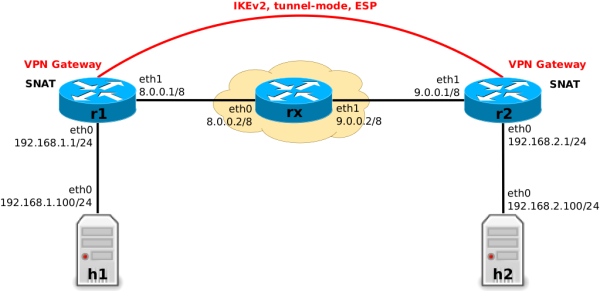
It is better to have a practical example as basis for further diving into the topic. Here I will use a site-to-site VPN setup, which is created between two VPN gateways r1 and r2 (IPsec, tunnel-mode, IKEv2, ESP, IPv4) as shown in Figure 4.
It can be roughly compared to the strongSwan KVM Test ikev2/net2net-psk setup.
The VPN tunnel will connect the local subnets behind r1 and r2. Additionally, both r1 and r2 operate as SNAT edge routers when forwarding non-VPN traffic, but not for VPN traffic. This creates the necessity to distinguish between VPN and non-VPN packets in Nftables rules, but more on that later. The router rx is just a placeholder for an arbitrary cloud (e.g. the Internet) between both VPN gateways.
- r1: swanctl.conf
connections {
  gw-gw {
    local_addrs  = 8.0.0.1
    remote_addrs = 9.0.0.1
    local {
      auth = psk
      id = r1
    }
    remote {
      auth = psk
      id = r2
    }
    children {
      net-net {
        mode = tunnel
        local_ts  = 192.168.1.0/24
        remote_ts = 192.168.2.0/24
        esp_proposals = aes128gcm128
      }
    }
    version = 2
    mobike = no
    reauth_time = 10800
    proposals = aes128-sha256-modp3072
  }
}
secrets {
  ike-1 {
    id-1 = r1
    id-2 = r2
    secret = "ohCeiVi5iez36ieFu"
  }
}
- r2: swanctl.conf
connections {
  gw-gw {
    local_addrs  = 9.0.0.1
    remote_addrs = 8.0.0.1
    local {
      auth = psk
      id = r2
    }
    remote {
      auth = psk
      id = r1
    }
    children {
      net-net {
        mode = tunnel
        local_ts  = 192.168.2.0/24
        remote_ts = 192.168.1.0/24
        esp_proposals = aes128gcm128
      }
    }
    version = 2
    mobike = no
    reauth_time = 10800
    proposals = aes128-sha256-modp3072
  }
}
secrets {
  ike-1 {
    id-1 = r1
    id-2 = r2
    secret = "ohCeiVi5iez36ieFu"
  }
}
r1 and r220)
Execute command swanctl --load-all on r1 and r2 to load this configuration of Figure 5 into the charon daemon. Execute command swanctl --initate --child net-net on r1 to initiate the VPN connection between both gateways. This triggers the IKEv2 handshake with r1 as “initiator” and r2 as “responder”. On successful IKE handshake, the charon daemon feeds the SAs and SPs which define this VPN tunnel via Netlink socket into the kernel and thereby the tunnel is now up. You can use the iproute2 tool ip as low-level admin tool to show the SAs and SPs which currently exist in the
databases inside the kernel, see Figures 6 and 7.
root@r1:~# ip xfrm state
src 8.0.0.1 dst 9.0.0.1
        proto esp spi 0xc5400599 reqid 1 mode tunnel
        replay-window 0 flag af-unspec
        aead rfc4106(gcm(aes)) 0x8849c107d9f6972da27a5faef554a68b10f3b938 128
        anti-replay context: seq 0x0, oseq 0x9, bitmap 0x00000000
src 9.0.0.1 dst 8.0.0.1
        proto esp spi 0xcd7dff80 reqid 1 mode tunnel
        replay-window 32 flag af-unspec
        aead rfc4106(gcm(aes)) 0x3c0497d489904175bdb446f3e09ae4c3acaf5d45 128
        anti-replay context: seq 0x9, oseq 0x0, bitmap 0x000001ff
r1 with ip xfrm command
root@r1:~# ip xfrm policy
src 192.168.1.0/24 dst 192.168.2.0/24
        dir out priority 375423 ptype main
        tmpl src 8.0.0.1 dst 9.0.0.1
                proto esp spi 0xc5400599 reqid 1 mode tunnel
src 192.168.2.0/24 dst 192.168.1.0/24
        dir fwd priority 375423 ptype main
        tmpl src 9.0.0.1 dst 8.0.0.1
                proto esp reqid 1 mode tunnel
src 192.168.2.0/24 dst 192.168.1.0/24
        dir in priority 375423 ptype main
        tmpl src 9.0.0.1 dst 8.0.0.1
                proto esp reqid 1 mode tunnel
src 0.0.0.0/0 dst 0.0.0.0/0
        socket in priority 0 ptype main
src 0.0.0.0/0 dst 0.0.0.0/0
        socket out priority 0 ptype main
src 0.0.0.0/0 dst 0.0.0.0/0
        socket in priority 0 ptype main
src 0.0.0.0/0 dst 0.0.0.0/0
        socket out priority 0 ptype main
src ::/0 dst ::/0
        socket in priority 0 ptype main
src ::/0 dst ::/0
        socket out priority 0 ptype main
src ::/0 dst ::/0
        socket in priority 0 ptype main
src ::/0 dst ::/0
        socket out priority 0 ptype main
r1 with ip xfrm command
Just for completeness: To tear the the VPN tunnel down again, you would need to execute command
swanctl --terminate --child net-net to terminate the ESP tunnel (SPs and SAs get removed from the kernel databases) and then command swanctl --terminate --ike gw-gw to terminate the IKE connection/association (IKE_SA).
Packet Flow
Let's say the VPN tunnel in the example described above is now up and running. To start simple, let's also assume that we have not yet configured any Nftables ruleset on the VPN gateways r1 and r2. Thus, those two hosts do not yet do SNAT (we will do this later). The VPN will already work normally, which means any IP packet which is sent from any host in subnet 192.168.1.0/24 to any host in subnet 192.168.2.0/24 or vice versa will travel through the VPN tunnel.
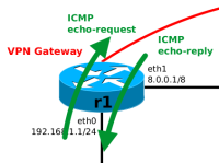
This means, packets which are traversing one of the VPN gateways r1 or r2 and are about to “enter the VPN tunnel” are being encrypted and then encapsulated in ESP and an outer IP packet. Packets which are “leaving the tunnel” are being decapsulated (the outer IP packet and ESP header are stripped away) and decrypted. Let's observe that on VPN gateway r1 by sending a single ping from h1 to h2, see Figure 8.
h1$ ping -c1 192.168.2.100
#       h1                                    h2
# 192.168.1.100 -> ICMP echo-request -> 192.168.2.100
# 192.168.1.100 <- ICMP echo-reply   <- 192.168.2.100
h1 to h2 traversing r1; ICMP echo-request entering VPN tunnel, ICMP echo-reply leaving VPN tunnel.
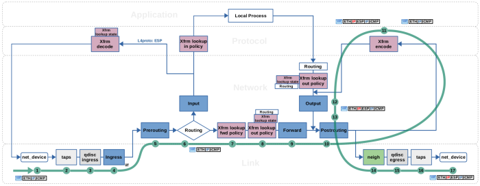
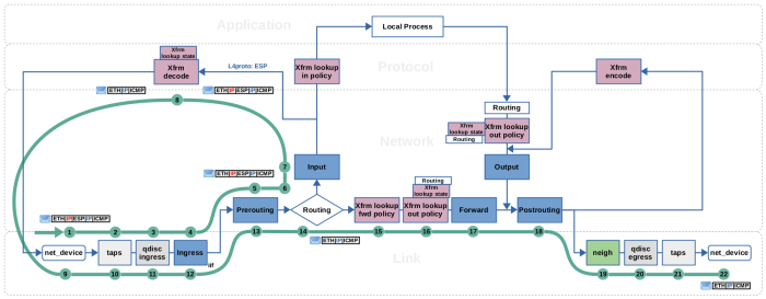
The following Figures 9 and
10 show in detail how the ICMP echo-request
and the corresponding ICMP echo-reply traverse the kernel network stack on
r1. Those Figures and the attached tables and descriptions below are the
result of me doing a lot of experimenting and reading in the kernel source code.
I used the Nftables trace and log features to make
chain traversal, and thereby Netfilter hook traversal, visible. Further, I
used ftrace to get a function_graph of the journey a network packet
takes through the kernel network stack while being encrypted/decrypted.
On some occasions I used gdb together with qemu+KVM to set
breakpoints within the kernel of a linux virtual machine and thereby
observe the content of data structures involved with a traversing packet.
While reading source code, the book Linux Kernel Networking - Implementation and Theory (Rami Rosen, Apress, 2014) proved to be a great
help to me to find orientation within the kernel network stack. I hope
this gives you a head start in case you intend to dive deep into that topic
yourself, too.
h1 → h2, r1 traversal, encrypt+encapsulate (click to enlarge)| Step | Encapsulation | iif | oif | ip saddr | ip daddr |
|
|---|---|---|---|---|---|---|
| 1 | eth0 | |eth| |ip|icmp| | eth0 | 192.168.1.100 | 192.168.2.100 |
|
| 2 | taps | |eth| |ip|icmp| | eth0 | 192.168.1.100 | 192.168.2.100 |
|
| 3 | qdisc ingress | |eth| |ip|icmp| | eth0 | 192.168.1.100 | 192.168.2.100 |
|
| 4 | Ingress (eth0) | |eth| |ip|icmp| | eth0 | 192.168.1.100 | 192.168.2.100 |
|
| 5 | Prerouting | |eth| |ip|icmp| | eth0 | 192.168.1.100 | 192.168.2.100 |
|
| 6 | Routing | |eth| |ip|icmp| | eth0 | … | 192.168.1.100 | 192.168.2.100 |
| 7 | Xfrm fwd policy | |eth| |ip|icmp| | eth0 | eth1 | 192.168.1.100 | 192.168.2.100 |
| 8 | Xfrm out policy | |eth| |ip|icmp| | eth0 | eth1 | 192.168.1.100 | 192.168.2.100 |
| 9 | Forward | |eth| |ip|icmp| | eth0 | eth1 | 192.168.1.100 | 192.168.2.100 |
| 10 | Postrouting | |eth| |ip|icmp| | eth1 | 192.168.1.100 | 192.168.2.100 |
|
| 11 | Xfrm encode | |eth|......|ip|icmp| | eth1 | … | … | |
| 12 | Output | |eth|ip|esp|ip|icmp| | eth1 | 8.0.0.1 | 9.0.0.1 |
|
| 13 | Postrouting | |eth|ip|esp|ip|icmp| | eth1 | 8.0.0.1 | 9.0.0.1 |
|
| 14 | neighbor | |eth|ip|esp|ip|icmp| | eth1 | 8.0.0.1 | 9.0.0.1 |
|
| 15 | qdisc egress | |eth|ip|esp|ip|icmp| | eth1 | 8.0.0.1 | 9.0.0.1 |
|
| 16 | taps | |eth|ip|esp|ip|icmp| | eth1 | 8.0.0.1 | 9.0.0.1 |
|
| 17 | eth1 | |eth|ip|esp|ip|icmp| | eth1 | 8.0.0.1 | 9.0.0.1 |
|
Steps (1) (2) (3) (4) (5): The ICMP echo-request packet from h1 to h2 is received on the eth0 interface of r1. It traverses taps (where e.g. Wireshark/tcpdump could listen), the ingress queueing discipline (network packet scheduler, tc), and the Netfilter Ingress hook of eth0 (where e.g. a flowtable could be placed). Then it traverses the Netfilter Prerouting hook.
Step (6): The routing lookup is performed. It determines that this packet
needs to be forwarded and sent out on eth1 and attaches this routing
decision to the packet.
Step (7): The Xfrm framework performs a lookup into the IPsec SPD,
searching for a matching forward policy (dir fwd SP). No match is
found and the packet passes.
Step (8): The Xfrm framework performs a lookup into the IPsec SPD,
searching for a matching output policy (dir out SP) and yes, because of its
source and destination IP addresses 192.168.1.100 and 192.168.2.100 the packet
matches, see Figure 7.
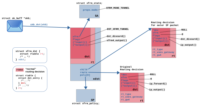
An IPsec SA is resolved (see Figure 6), which corresponds to
the matching SP. The Xfrm framework detects, that tunnel-mode is configured in
this SA. Thus, it now performs yet another routing lookup, this time for the (future) outer
IPv4 packet, which will later encapsulate the current packet. A “bundle” of
transformation instructions for this packet is assembled, which contains the
original routing decision from step (6), the SP, the SA, the routing decision
for the future outer IP packet and more. It is attached to the packet,
replacing the attached routing decision from step (6).
Steps (9) (10): The packet traverses the Netfilter Forward and Postrouting hooks.
Step (11): The Xfrm framework transforms the packet
according to the instructions in the attached “bundle”. In this case this
means encapsulating the IP packet into a new outer IP packet
with source IP address 8.0.0.1 and destination IP addresses 9.0.0.1
and then encapsulating the inner IP packet into ESP protocol and encrypting it and its
payload. After that the transformation instructions are removed from the
“bundle”, leaving only the routing decision for the new outer IP packet
attached to the packet.
Steps (12) (13) (14) (15) (16) (17): The packet is re-inserted into the local
output path. It traverses the Netfilter Output hook and then again the
Netfilter Postrouting hook. Then it traverses the neighboring
subsystem which in this case resolves the next hop gateway ip address
8.0.0.2 from the routing decision attached to this packet into a MAC address
(by doing ARP lookup, if address not yet in cache).
Finally, it traverses the egress queueing discipline (network packet
scheduler, tc), taps (where e.g. Wireshark/tcpdump could listen) and
then is sent out on eth1.
The output interface oif of the packet, since determined by the routing decision(s) in steps (6) and (8), always stays eth1 when you check for it in an Nftables rule within one of the Netfilter hooks coming after that. This is what it means that the Xfrm framework does not use virtual network interfaces. If virtual network interfaces would instead be used here (e.g. a vti interface named vti0), then oif would be vti0 in steps (9) and (10) instead of eth1, but oif would still be eth1 in steps (12) and (13).
h2 → h1, r1 traversal, decrypt+decapsulate (click to enlarge)| Step | Encapsulation | iif | oif | ip saddr | ip daddr |
|
|---|---|---|---|---|---|---|
| 1 | eth1 | |eth|ip|esp|ip|icmp| | eth1 | 9.0.0.1 | 8.0.0.1 |
|
| 2 | taps | |eth|ip|esp|ip|icmp| | eth1 | 9.0.0.1 | 8.0.0.1 |
|
| 3 | qdisc ingress | |eth|ip|esp|ip|icmp| | eth1 | 9.0.0.1 | 8.0.0.1 |
|
| 4 | Ingress (eth1) | |eth|ip|esp|ip|icmp| | eth1 | 9.0.0.1 | 8.0.0.1 |
|
| 5 | Prerouting | |eth|ip|esp|ip|icmp| | eth1 | 9.0.0.1 | 8.0.0.1 |
|
| 6 | Routing | |eth|ip|esp|ip|icmp| | eth1 | 9.0.0.1 | 8.0.0.1 |
|
| 7 | Input | |eth|ip|esp|ip|icmp| | eth1 | 9.0.0.1 | 8.0.0.1 |
|
| 8 | Xfrm decode | |eth|......|ip|icmp| | eth1 | … | … | |
| 9 | eth1 | |eth| |ip|icmp| | eth1 | 192.168.2.100 | 192.168.1.100 |
|
| 10 | taps | |eth| |ip|icmp| | eth1 | 192.168.2.100 | 192.168.1.100 |
|
| 11 | qdisc ingress | |eth| |ip|icmp| | eth1 | 192.168.2.100 | 192.168.1.100 |
|
| 12 | Ingress | |eth| |ip|icmp| | eth1 | 192.168.2.100 | 192.168.1.100 |
|
| 13 | Prerouting | |eth| |ip|icmp| | eth1 | 192.168.2.100 | 192.168.1.100 |
|
| 14 | Routing | |eth| |ip|icmp| | eth1 | … | 192.168.2.100 | 192.168.1.100 |
| 15 | Xfrm fwd policy | |eth| |ip|icmp| | eth1 | eth0 | 192.168.2.100 | 192.168.1.100 |
| 16 | Xfrm out policy | |eth| |ip|icmp| | eth1 | eth0 | 192.168.2.100 | 192.168.1.100 |
| 17 | Forward | |eth| |ip|icmp| | eth1 | eth0 | 192.168.2.100 | 192.168.1.100 |
| 18 | Postrouting | |eth| |ip|icmp| | eth0 | 192.168.2.100 | 192.168.1.100 |
|
| 19 | neighbor | |eth| |ip|icmp| | eth0 | 192.168.2.100 | 192.168.1.100 |
|
| 20 | qdisc egress | |eth| |ip|icmp| | eth0 | 192.168.2.100 | 192.168.1.100 |
|
| 21 | taps | |eth| |ip|icmp| | eth0 | 192.168.2.100 | 192.168.1.100 |
|
| 22 | eth0 | |eth| |ip|icmp| | eth0 | 192.168.2.100 | 192.168.1.100 |
|
Steps (1) (2) (3) (4) (5): The ICMP echo-reply sent from h2 back to h1 is received on eth1 interface of r1 in its encrypted+encapsulated form. It traverses taps (where e.g. Wireshark/tcpdump could listen), the ingress queueing discipline (network packet scheduler, tc), and the Netfilter Ingress hook of eth1 (where e.g. a flowtable could be placed). Then it traverses the Netfilter Prerouting hook.
Steps (6) (7): The routing lookup is performed. In this case here, the routing subsystem determines that this packets destination IP 8.0.0.1 matches the IP address of interface eth1 of this host r1. Thus, this packet is destined for local reception and the lookup attaches an according routing decision to it. As a result, the packet then traverses the Netfilter Input hook.
Steps (8) (9): The Xfrm framework has a layer 4 receive handler waiting for incoming ESP
packets at this point. It parses the SPI value from the ESP header of the
packet and performs a lookup into the SAD for a matching IPsec SA (lookup
based on SPI and destination IP address). A matching SA is found, see Figure
6, which
specifies the further steps to take here for this packet. It is decrypted and
the ESP header is decapsulated. Now the internal IP packet becomes visible.
The SA specifies tunnel-mode, so the outer IPv4 header is decapsulated. A lot
of packet meta data is changed here, e.g. the attached routing decision (of
the outer IP packet, which is now removed) is stripped away, the reference to
connection tracking is removed, and a pointer to the SA which has been used
here to transform the packet is attached (via skb extension
struct sec_path). As a result, other kernel components can later
recognize that this packet has been decrypted by Xfrm. Finally, the packet is
now re-inserted into the OSI layer 2 receive path of eth1.
Steps (10) (11) (12) (13): Now history repeats… the packet once again traverses
taps, the ingress queueing discipline and the Netfilter Ingress hook of
eth1. Then it traverses the Netfilter Prerouting hook.
Step (14): The routing lookup is performed. It determines that this
packet needs to be forwarded and sent out on eth0 and attaches this routing decision
to the packet.
Step (15): The Xfrm framework recognizes, that this packet has been transformed
according to the SA, whose pointer is still attached to the packet (within skb extension struct sec_path).
It checks if a forward policy (dir fwd SP) exists which corresponds to this SA, and yes,
a match is found here, see Figure 7. So the packet passes.
Step (16): The Xfrm framework performs a lookup into the IPsec SPD, searching for a matching
output policy (dir out SP). No match is found. Still, the packet passes.
The idea of the output policy is to detect packets which shall be encrypted with IPsec.
Packets which do not match, just pass.
Steps (17) (18) (19) (20) (21) (22): The packet traverses the Netfilter
Forward and Postrouting hooks. Then it traverses the neighboring
subsystem which does resolve the destination IP address, which is now
192.168.1.100, into a MAC address (by doing ARP lookup, if address not yet
in cache). Finally, it traverses the egress queueing discipline, taps
and then is sent out on eth0.
The input interface iif of the packet during this whole traversal stays eth1 when you check for it in an Nftables rule within one of the Netfilter hooks21).
This is what it means that the Xfrm framework does not use virtual network interfaces. If virtual network interfaces would instead be used here (e.g. a vti interface named vti0), then iif would still be eth1 in steps (4), (5) and (7), but would be vti0 in steps (12), (13) and (17).
SNAT, Nftables
Now to add the SNAT behavior to r1 and r2, we apply the following
Nftables ruleset on r1 and r2:
nft add table nat
nft add chain nat postrouting { type nat hook postrouting priority 100\; }
nft add rule nat postrouting oif eth1 masquerade
nft add table filter
nft add chain filter forward { type filter hook forward priority 0\; policy drop\; }
nft add rule filter forward iif eth0 oif eth1 accept
nft add rule filter forward iif eth1 oif eth0 ct state established,related accept
This ruleset is identical on both hosts.
What is the resulting change in behavior? Well, for non-VPN traffic now all works as intended. Hosts h1
and h2 e.g. can now finally ping rx22) and from rx point of view it looks like the ping came from r1 or respectfully r2.
However, let's take another look at the example from Figure 9 above (the ICMP echo-request h1 → h2 traversing r1) and examine how the behavior differs now: In step (10) in the example the still unencrypted ICMP echo-request packet traverses the Netfilter Postrouting hook and thereby the Nftables postrouting chain. Because of the masquerade rule, its source IP address is now replaced with the address 8.0.0.1 of the eth1 interface of r1.
Resulting from that, this packet now does not match the IPsec output policy anymore. Thus, it won't get encrypted+encapsulated! Obviously that is not our intended behavior, but let's first dig deeper to understand what actually happens here: In step (8) this packet still had its original source and destination IP addresses 192.168.1.100 and 192.168.2.100 and thereby matched to output policy selector src 192.168.1.0/24 dst 192.168.2.0/24 (see Figure 7). Now in step (10), with its source IP address changed to 8.0.0.1 it does not match that output policy anymore. But wait! That Xfrm lookup for the output policy has already been done in step (8) and the “bundle” with transform instructions is already attached to the packet. Isn't the chaos complete now??? No, because the NAT implementation indeed is aware that this situation can occur. In case NAT actually changes something in the packet traversing the Postrouting hook (like in this case the source IP address), then it calls function nf_xfrm_me_harder()23) which essentially does the whole step (8) all over again. Thus, the Xfrm lookup for a matching output policy is actually repeated in this case. For the ICMP echo-request packet in our example this actually means that the original “plain” routing decision is being restored and and the “bundle” with the Xfrm instructions is removed.
Ok, now we understand it … the ping is natted, but then sent out plain and unencrypted. That is not what we want. Further, this ping is now anyway doomed to fail, because rx does not know the route to the target subnet and even if it did, r2 would then drop the packet because it also is now configured as SNAT router and thereby drops incoming new connections in the forward chain.
How to fix that? It is our intended behavior, that network packets from subnet
192.168.1.0/24 to subnet 192.168.2.0/24 and vice versa shall travel through the
VPN tunnel and shall not be natted. Also, it shall be possible to establish connections
with connection oriented protocols (e.g. TCP24))
in both ways through the VPN tunnel. One simple way to achieve this behavior is to add these two rules on r1:
- r1
nft insert rule nat postrouting oif eth1 ip daddr 192.168.2.0/24 accept
nft add rule filter forward iif eth1 oif eth0 ip saddr 192.168.2.0/24 ct state new accept
For the first rule I used insert instead of add, so that it is inserted as first
rule of the postrouting chain, thus BEFORE the masquerade rule. Obviously we
need to do the equivalent (but not identical!) thing on r2:
- r2
nft insert rule nat postrouting oif eth1 ip daddr 192.168.1.0/24 accept
nft add rule filter forward iif eth1 oif eth0 ip saddr 192.168.1.0/24 ct state new accept
The complete rulesets then look like this: Nftables rulesets on r1 on r2
Let's look at the example from Figure 9 again (ICMP echo-request h1 → h2 traversing r1): In step (10) when traversing the postrouting chain, now the inserted rule oif eth1 ip daddr 192.168.2.0/24 accept prevents that the packet is natted by accepting it and thereby preventing that it traverses the masquerade rule25). The remaining steps of the r1 traversal now happen exactly as in the example and we reached our intended behavior.
When the ICMP echo-request packet is received by and traverses r2, the behavior follows the same principles as described in the example in Figure 10 above (ICMP echo-reply h2 → h1 traversing r1). However, it is necessary to add the rule iif eth1 oif eth0 ip saddr 192.168.1.0/24 ct state new accept to the forward chain, because from r2 point of view this is a packet of a new incoming connection and those we want to allow for packets which traveled through the VPN tunnel, but not for other packets.
Distinguish VPN/non-VPN traffic
No matter if your idea is to do NAT or your intentions are other kinds of packet manipulation or packet filtering, it all boils down to distinguishing between VPN and non-VPN traffic.
The Nftables rulesets I applied to r1 and r2 in the example above are a crude way to do that, but it works. It is crude, because the distinction is made solely based on the target subnet (the destination IP address) of a traversing packet. Further, the added rule in the forward chain now allows incoming new connections from WAN side, if the source address is from the peer's subnet. However, the rule does not check, whether that traffic has actually been received via the VPN tunnel! Essentially, it opens a hole in the stateful firewall. And there are further issues which this crude solution does not address: What happens when the VPN tunnel is not up, but the mentioned Nftables rulesets are in place? What happens if the subnets behind the VPN gateways are not statically configured but instead are part of dynamic IKE negotiation during IKE handshake? …
As I mentioned above, things would be easier, if the Xfrm framework would use virtual network interfaces, because those then could serve as basis for making this distinction.
Several means have been implemented to address those kind of issues:
- Strongswan provides an optional
_updownscript which is called each time when the VPN tunnel comes up or goes down. You can use it to dynamically set/remove the Nftables rules you require. The default version of that script already sets some Iptables rules for you, but depending on your system (kernel/Nftables version) this can create more problems than it solves. And who says that these default rules do fit well with your intended behavior? Thus, if you use this, you probably need to replace the default script with your own version. - Nftables offers IPSEC EXPRESSIONS (syntax
ipsec {in | out} [ spnum NUM ] …) which make it possible to determine whether a packet is part of the VPN context or not. I published a follow-up article which covers that topic in detail: Nftables - Demystifying IPsec expressions. - Nftables offers “markers” which you can set and read on traversing packets (syntax
meta mark) which can help you to mark packets (set the mark) as being part of the VPN context in one hook/chain and in a later hook/chain you can read the mark again. - So-called
vtiorxfrmvirtual network interfaces can optionally be used “on top” of the default Xfrm framework behavior.
Context
The described behavior and implementation has been observed on a Debian 10 (buster) system with using Debian backports on amd64 architecture.
- kernel:
5.10.46-4~bpo10+1 - nftables:
0.9.6-1~bpo10+1 - strongswan:
5.7.2-1+deb10u1
Feedback
Feedback to this article is very welcome! Please be aware that I did not develop or contribute to any of the software components described here. I'm merely some developer who took a look at the source code and did some practical experimenting. If you find something which I might have misunderstood or described incorrectly here, then I would be very grateful, if you bring this to my attention and of course I'll then fix my content asap accordingly.
References
published 2020-05-30, last modified 2022-08-14
eth (ethernet) and the ip header. I just show it like this here to emphasize WHERE in the packet the ESP header and the outer IP header are being inserted.|eth|ip|esp-header|ip|tcp|payload|esp-trailer|.nhrpd of the FRR routing protocol engine, which is used in DMVPN setups.man 8 ip-xfrmip xfrm policy.sec_pathUDP_ENCAP or else it won't receive any IKE packets on port 4500. But that is an implementation detail.gre interfaces, but they represent an entirely different concept and protocol (GRE protocol) which is e.g. used to build DMVPN setups. That is an advanced topic which works a little different than the “normal” IPsec VPN which I describe here.r1 and r2 here merely is an example configuration which helps me to elaborate on the interaction between Strongswan, Xfrm and Netfilter+Nftables. It is NOT necessarily a good setup to be used in the real world out in the field! To keep things simple I e.g. work with PSKs here instead of certificates, which would already be a questionable decision regarding a real world appliance.r1 and r2, because routers in the Internet commonly do not know the routes to private subnets behind edge routers.

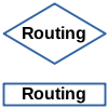 The routing lookup is performed for incoming as well as local outgoing packets, see Figure
 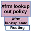 This action is performed for forwarded as well as for local outgoing packets after the routing lookup, see Figure
  This is where packets which shall travel through the VPN tunnel are being encrypted and encapsulated. The Xfrm framework transforms a packet according to the instructions in the “bundle” attached to it. A function pointer within the bundle makes sure, that the packet takes a “detour” into this transformation code after traversing the Netfilter Postrouting hook. For IPv4 packets, the entry function which leads the packet on this path is
  This is where packets which have been received through the VPN tunnel are being decrypted and decapsulated. If an IP packet on the local input path contains an ESP packet, then the Xfrm framework performs a lookup into the SAD (Xfrm lookup state), based on the SPI
 If already decrypted+decapsulated packets arrive here,
they must match the “input policy” (
 If already decrypted+decapsulated packets arrive here,
they must match the “forward policy” (